
Using ArcGIS CityEngine for GeoDesign on McMaster Campus: Part 2
This article continues from the initial two steps outlined in Part 1, where an initial 3D environment for the McMaster University campus was constructed using digital elevation data, aerial imagery, and 3D models for campus buildings available for download from the SketchUp 3D Warehouse website. In this second part, the remaining steps are outlined, describing how CityEngine’s modelling capabilities are used to complete the 3D environment by generating new models for buildings that could not be obtained from the 3D Warehouse.
Step 3) Construct the 3D environment for McMaster University – polygonal modelling:
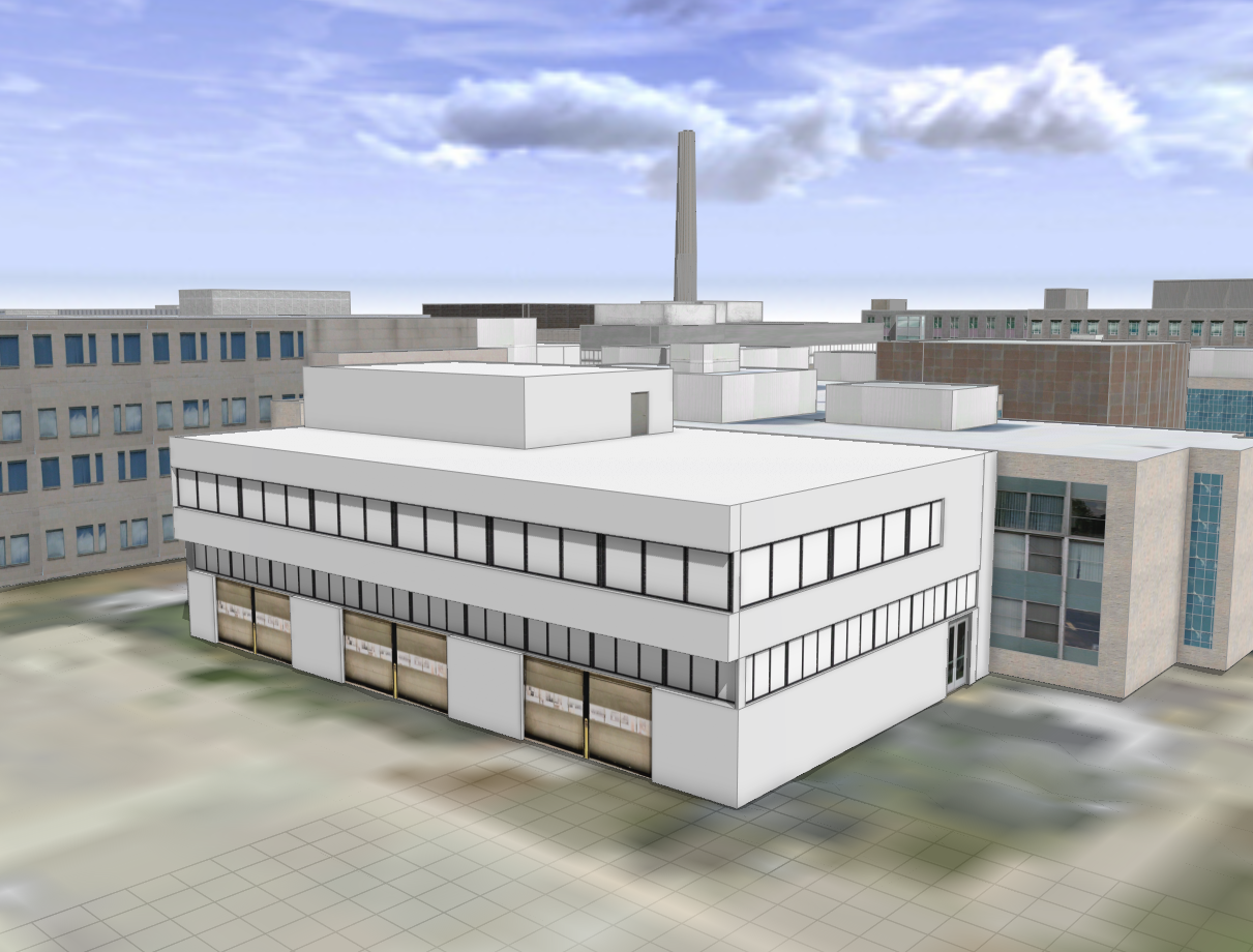
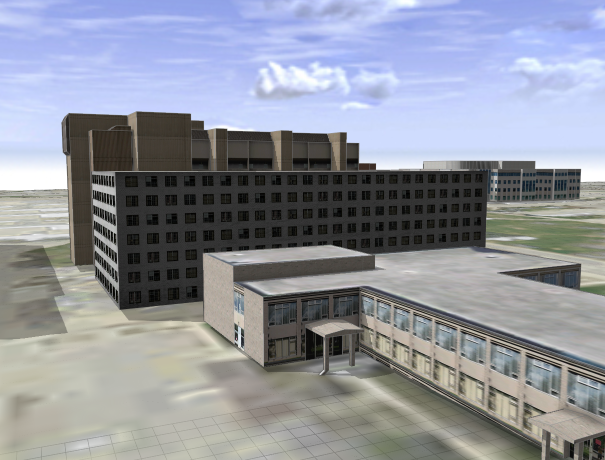
Buildings that were not available in 3D Warehouse were created through polygonal modelling in CityEngine. Firstly, building footprints were extruded to the mass models by using the Push Pull tool. Then, the Rectangular Shape Creation tool was used to create the doors and windows. Finally, texture images were assigned to the walls, roofs, doors and windows by using the Shape Texturing tool. These texture images were derived from the campus building photos and Google images. When assigning the textures to walls or roofs, it would be a uniform texturing and the mode was set to Dimension (“Tutorial 14a,” n.d.). Whereas assigning the textures to doors or windows, the mode was set to Stretch to polygon so that the textures would fit in with the frames (“Tutorial 14a,” n.d.). As demonstrated in Fig. 9-11, Gerald Hatch Centre and Nuclear Research Building were created through polygonal modelling.
Step 4) Planning and Geodesign at McMaster University:
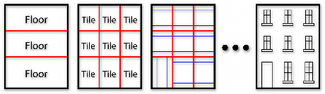
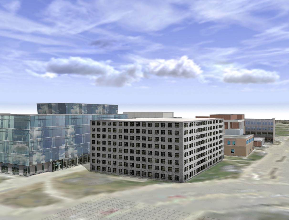
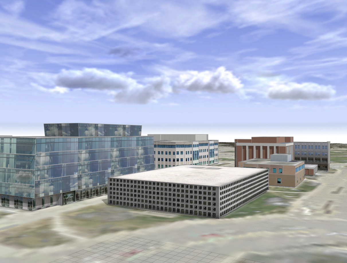
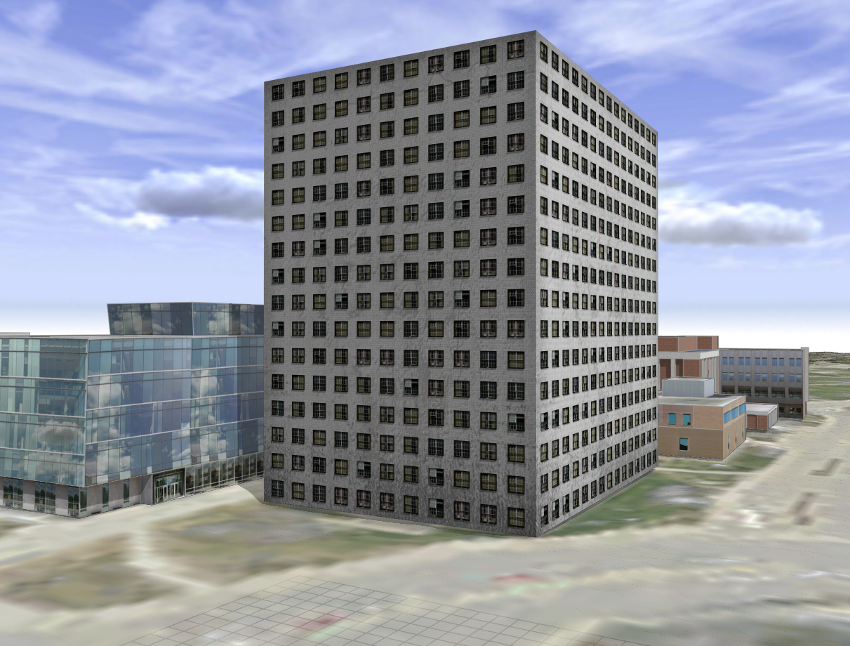
The planning analyses discovered two optimal lots for developing new buildings. The first lot is located between the McMaster Divinity College and Life Science Building. The second lot is located at the temporary building 13 or T13. New buildings were generated through CGA rule coding, which is a dedicated scripting language unique to CityEngine (“Tutorial 1,” n.d.). Firstly, the two lot shapes were created by using the Polygonal Shape Creation tool. A new rule file was created in the CGA rule editor, which would be applied to the shapes for the proposed lots. According to the building attributes defined at the beginning of the rule file, CGA rule extrudes the lot shapes to the mass models and decomposes the entire building into different faces, floors, tiles and elements (such as walls, doors and windows) (Fig. 12). A tile is typically comprised of the wall and door/window elements (“Tutorial 6,” n.d.). Then, the CGA rule prepares the UV coordinate projections on the element facades and scales the texture images to ensure they fit nicely (“Tutorial 6,” n.d.). Lastly, the CGA rule assigns the textures to each of the elements. The dirt map texture was assigned to the wall element to make the building look dirty in the cracks and corners (“Tutorial 6,” n.d.). In addition, a function was configured in the rule that allows the users to switch between the low and high level of details. The high level of detail inserts a realistic 3D frame to the window element, whereas the low level of detail only loads a simple plane texture. As demonstrated in Fig. 13&14, two new buildings were generated on the proposed lots by clicking on the Generate button.
Create models through polygonal modelling versus CGA rule coding:
Polygonal modelling is a very user-friendly method because it does not require any scripting and ensures the users to create perfect shapes (such as rectangles) with lots of guidance. Thus, polygonal modelling method was applied to create the models that replicate the existing campus buildings. However, it is very time-consuming and compared to the models from 3D Warehouse, the polygonal modelling has very limited capability to create a realistic building model.
CGA rule coding/modelling method is more difficult to create the models for the existing campus buildings, especially for the new users, because it requires lots of information about the building attributes (such as building height, floor height and window size). For this project, it is very difficult to obtain this information for all the campus buildings from either direct measurements or Facility Services. Since most of the campus buildings are fancy and creative, scripts would be very complicated because a small variation in the building structures or inserting an additional element to the building (such as subwindows) would make the scripting very complicated. However, it is well-suited to simulate the building developments because there are no true building attributes for a new building and we only need a simple building model. In addition, users can change the building attributes outside the CGA rule editor and examine the different designs of building structures (Fig. 15 & 16).
Step 5) Export and publish:
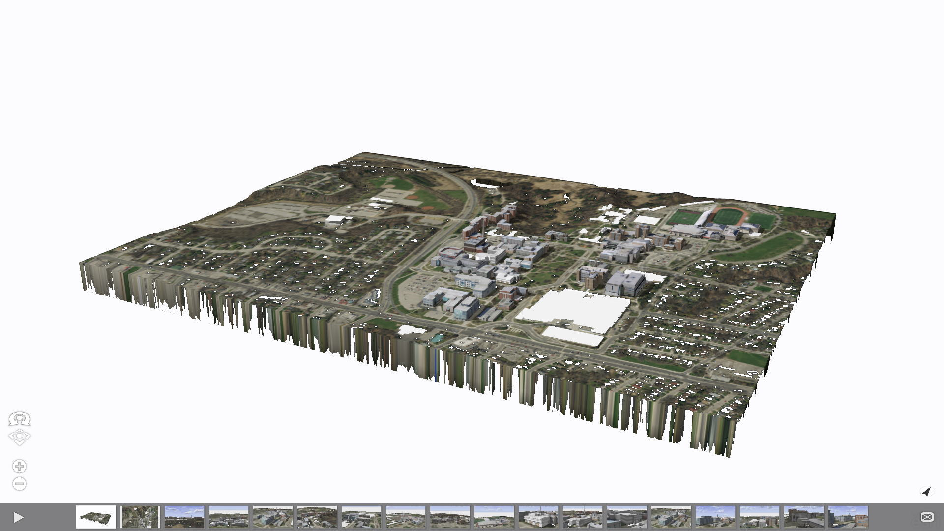
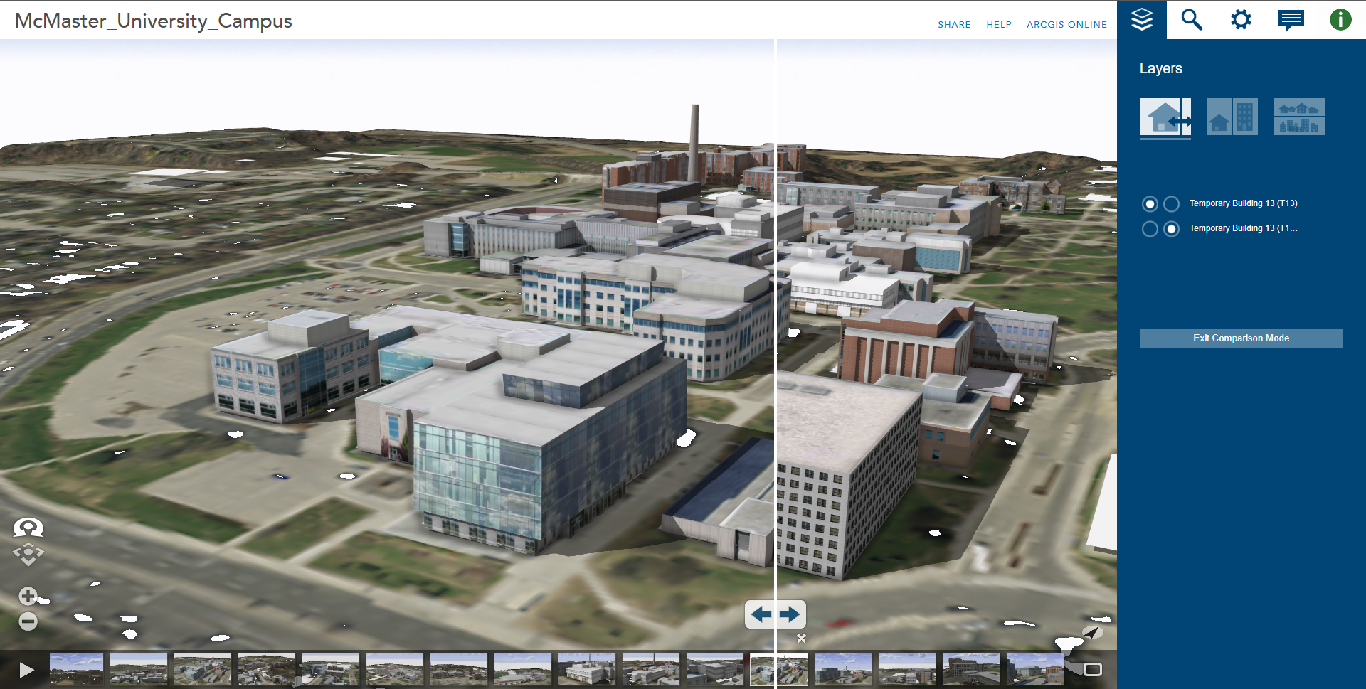
Models were exported and published as a CityEngine web scene in ArcGIS Online (Fig. 17). The view settings (such as shadow and ambient occlusion), scene light and panorama settings were exported together with the models. “Using ArcGIS CityEngine for GeoDesign on McMaster Campus – CityEngine Web Scene” can be accessed from https://bit.ly/35dUBxD. Click the Play button to play a tour through all the bookmarks. The swipe view was utilized to simulate building developments (Fig. 18).
Conclusion:
In conclusion, CityEngine has demonstrated superior capability and performance in a local-scale planning project. This project illustrates that CityEngine can promote effective workflows for planning and geodesigning of 3D environments in various scales. This project is a significant stepstone for incorporating CityEngine in future planning projects at McMaster University.
Bibliography:
Tutorial 1: Essential skills. (n.d.). ArcGIS CityEngine. https://doc.arcgis.com/en/cityengine/2020.0/tutorials/tutorial-1-essential-skills.htm
Tutorial 6: Basic shape grammar. (n.d.). ArcGIS CityEngine. https://doc.arcgis.com/en/cityengine/2020.0/tutorials/tutorial-6-basic-shape-grammar.htm
Tutorial 14a: Basic polygonal modelling. (n.d.). ArcGIS CityEngine. https://doc.arcgis.com/en/cityengine/2020.0/tutorials/tutorial-14a-basic-polygonal-modeling.htm