
Batch Processing ACSII Files using Model Builder and Georeferencing Tools
Introduction
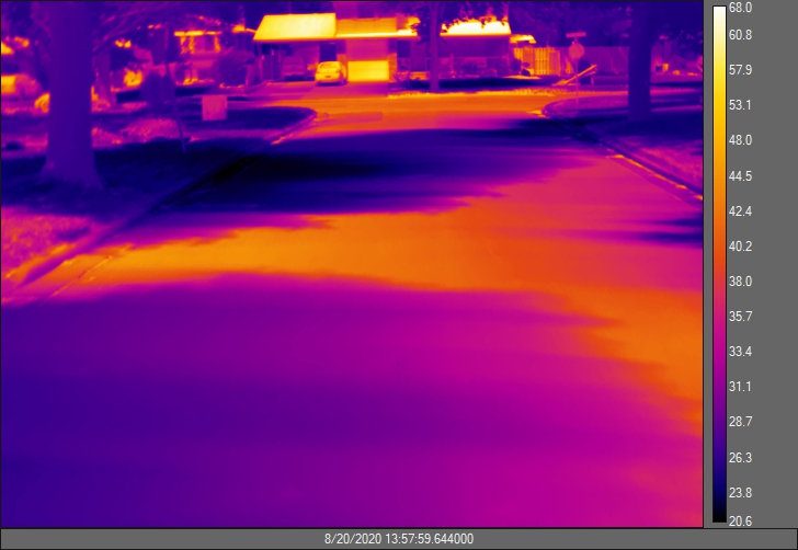
For the past few months I had the pleasure to be working with my supervisor to construct a series of 2D thermal composites using ArcMap from a set of 3D images taken by a forward-looking infrared (FLIR) thermal camera in the field. The difficulty of the project comes from the fact that our images do not have embedded GPS coordinates, therefore it was almost impossible to re-project the images using the thermal camera as a reference point for spatial information. While it might be possible to classify each pixel of the images to be stored as a numerical value in a raster, it is challenging to assign appropriate spatial units and coordinates to these new pixels (e.g., how can we confirm the resolution of the composites is the same as the original file, and how do we make sure each set of thermal composites is in the correct position in relative to each other).
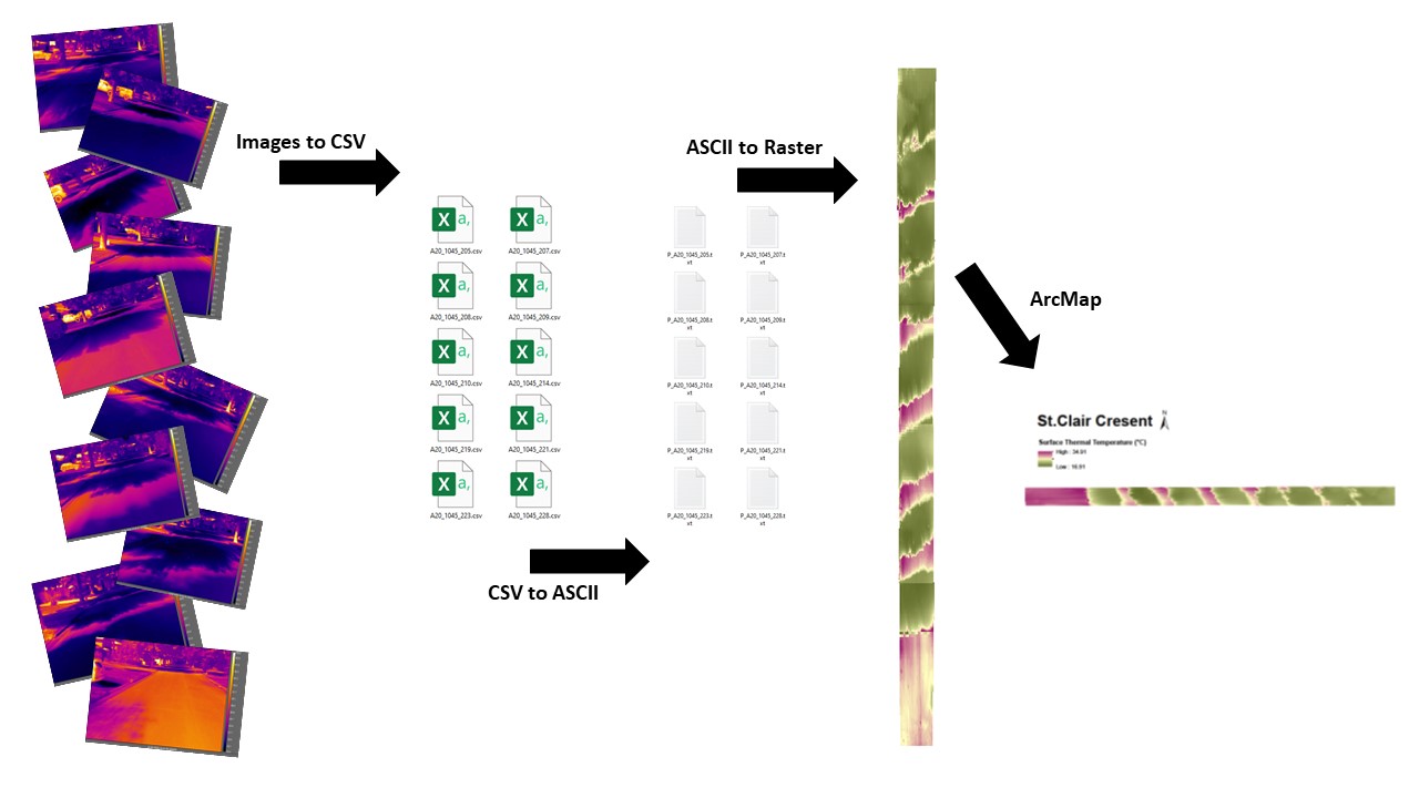
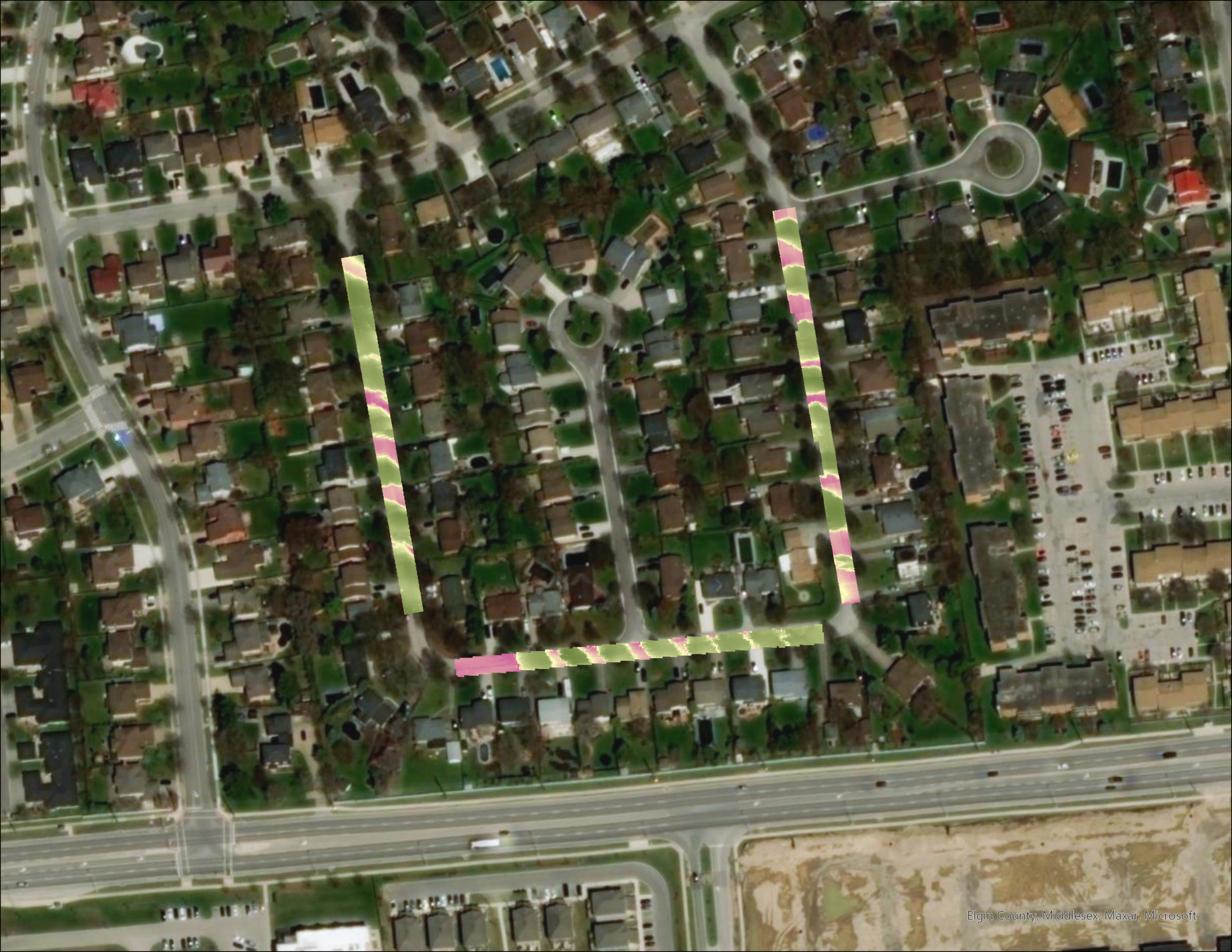
It was fortunate that my supervisor Austine and Dr. Voogt were able to come up with a solution to re-project and correct the images using geometry, and converted the images into a set of ASCII files that I can process within ArcMap. My tasks were to convert all of the ASCII files into raster, inspect their quality, manually align and edit the raster to produce a map with a series of thermal composites. These composites represent the surface temperature of the roads where my supervisor collected the data. After some practice dealing with the ASCII files as well as raster data that have no spatial information, I learned that there are some very useful tools in ArcMap/ArcGIS Pro that can be used to automate a lot of the work that would have been very time consuming if done manually.
Using the Model Builder to Automate Repetitive Workflow
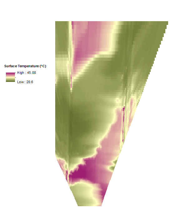
Since the first step of my task was to import all the ASCII files and convert them into raster using the ASCII to Raster tool from the conversion toolbox, it would have been very time consuming to convert 50 files. Each has to be done separately because the tool only processes one file at a time. Based the number of files I needed to process, I started looking for an automated way to quickly navigate through this repetitive process.
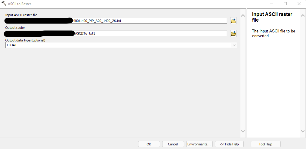
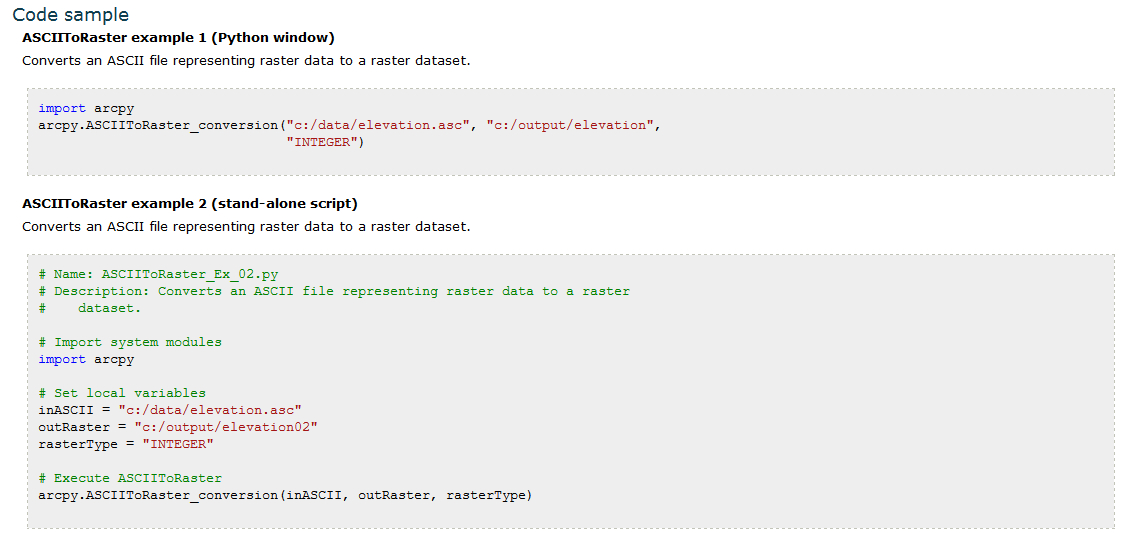
One method I considered was to use coding in the Python, using the Python sample provided in the tool’s documentation, as well as guidance from the Esri Community Forum. Since that I’m not proficient in Python, I chose not to try to batch process the ASCII to Raster tool this way. However, using Python for automation is an approach I hope to explore in the future, for example, using ArcGIS Notebooks.
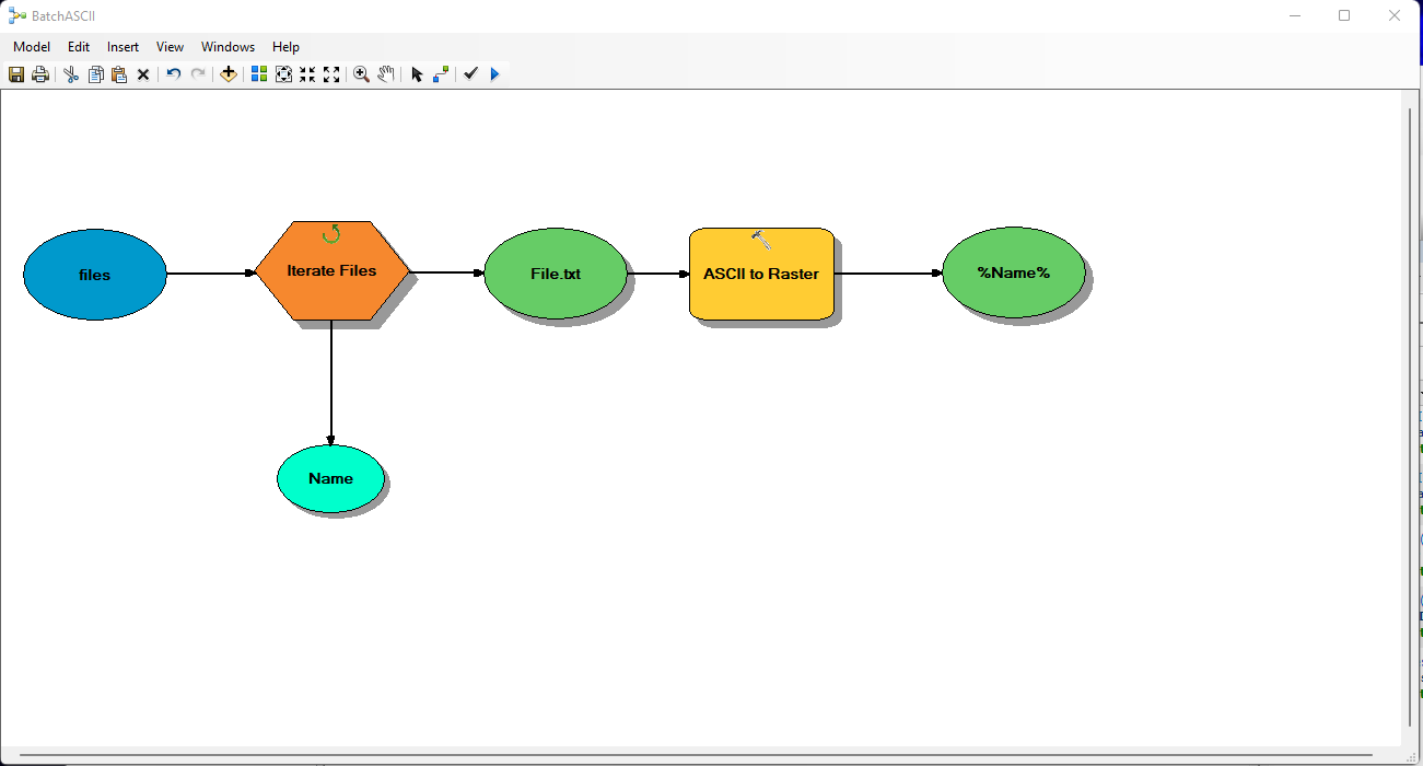
As an alternative approach, I chose to create a workflow using Model Builder in ArcGIS Pro. After a few trials and some testing, this worked perfectly. My first intention for the workflow was as follows:
- Input the ASCII file in a selected folder
- Convert into Raster (Format: tiff; Type: Long)
- Save the output in the selected folder
- Repeat until all the ASCII files are converted
This simple workflow didn’t work initially, because I needed a few more steps to enable the model to recognize the directory and the multiple source files that I want it to process. For this, I need to use an Iterator to enable the model tp “batch process” multiple files instead of reading only one file. I chose to use the “Files” Iterator because my ASCII files were stored as simple txt. files. I then dragged the folder into the model, selected it as my “Folder” in the iterator, and specified the “txt” File Extension so that the iterator would only process the text files I needed it to import.
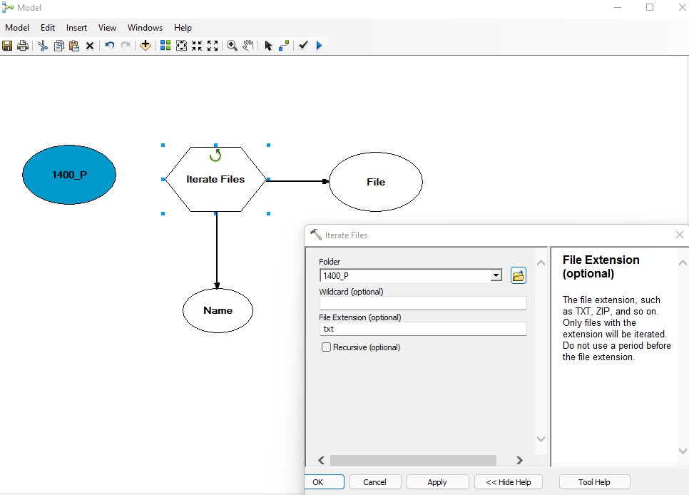
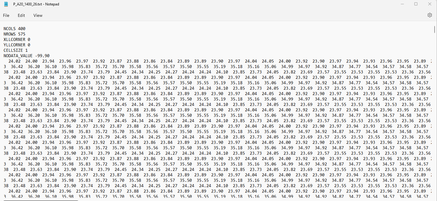
However, this step didn’t work out as smoothly as I initially expected because some files were missing. I spent some time trying to identify the error and it turns out to be a “Traceback” error because the iterator doesn’t recognize files that have names longer than 13 characters (e.g. P_A20_1400_26.txt would work, but P_A20_1400_101.txt wouldn’t). To work around this error, I would have to rename all my files to be as short as possible.
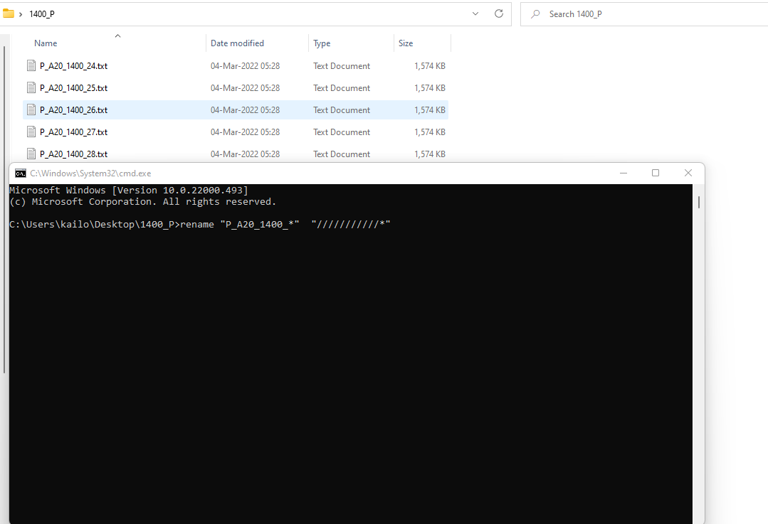
To quickly rename my files, I used a Windows Command Prompt (cmd) opened in the folder containing the files, and executed the following line of code:
rename "P_A20_1400_*" "///////////*" In this code, the first argument is the pattern of the filename I want to rename (“P_20_1400_*”), and the eleven “/” characters in the second argument will cause the corresponding characters in the pattern to be replaced with nothing (i.e., I simply wanted the first eleven characters to be removed). For example, this command would change the filename “P_A20_1400_26.txt” to “26.txt”.
This extra step allowed me to shortern my file names so now the iterator can correctly read and import my files accordingly. We can save the output raster into a designated path, saving them as %Name% would allow the iterator to name each processed raster individually according to the input ASCII file, this is avoids any hassle of renaming them in ArcMap/Arcgis Pro individually.
The Model Builder can not only be used to batch process multiple ASCII files into raster, but it can also be used to change the symbology of the raster (instead of using the the default greyscale display). Following a sample in a post on StackExchange, I was able to create another model and save it in my toolbox to process all of my datasets. It was also possible to automate this process in Python using ArcPy, but I found that the Model Builder was a better tool to visualize the workflow, and it’s easier for me to identify where an error can occur.
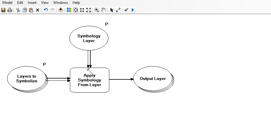
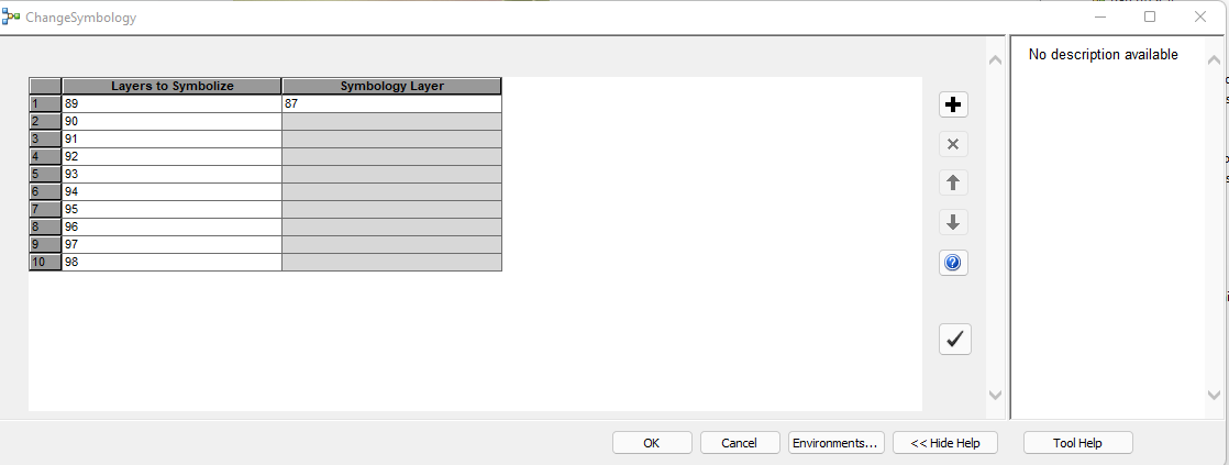
Once we save the model in a toolbox, and double-click on it to open it in ArcGIS, a window will pop up showing the parameters for the tool. In this case, we need to specify one layer to be used as the “Symbology Layer”, and all the rasters to be updated with its symbology in the “Layers to Symbolize” parameter. With this model, it is simple to have the symbology of many raster layers automatically updated to use symbology copied from a single layer that serves as the source of symbology. It is much more efficient than manually updating the symbology of each individual raster.
Using the Georeferencing Tool to Position Raster With No Spatial Reference
Since our ASCII files didn’t have coordinates and projection, it means our raster wouldn’t have coordinates either. This was a major challenge we had to overcome, because having no coordinates made processing these data much more difficult as they don’t have control points that we can use to anchor, or stitch each raster together to create a composite. However, our focus was not about correctly projecting the raster to create an overlay over a satellite image. My next step in this task was to merge and align each raster visually so that these rasters can be treated as a single composite image to be used for further analysis by my supervisor. This process required a lot of visual correcting and could not be automated because not all of the raster were usable, and having no spatial reference in the pixels means we couldn’t use a variety of tools such as Select by Attributes (Queries), Spatial Join, or Merge Mosaic Dataset Items.
One method of changing the position of these raster was through editing the original ASCII File, by changing the values in “XLLCORNER” and “YLLCORNER” entries . This method would be very time consuming for very large dataset and wouldn’t be effective for a raster that need to be rotated and/or rescaled in order to align with other rasters.
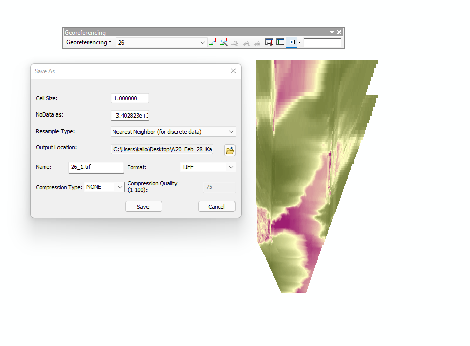
An alternative method I came up with was by using the Georeferencing Tool. While the original purpose of this tool is to position different sources of raster data over an existing map or satellite image, I found this tool was equally effective for what I was trying to achieve. There were four major functions that are provided by the tool:
- Add Control Points (allows positioning the raster by selecting two control points)
- Rotate (manually rotate the position of the raster)
- Shift (enables dragging the raster to anywhere you want them to be positioned)
- Scale (enlarge or shrink the raster)
To fix the position of the raster permanently, we need to save this by clicking on the the “Rectify” button. The “Redo” button in this tool is also called “Reset Tranformation”, and we can “Delete Links” if we need to delete control points that have been added.
It took me a few trials to successfully georeference a raster. After this step, we can add the new georeferenced layer to the map and remove the original raster. Repeating this step allowed me to align all of my rasters together by visually choosing control points, then I was able to merge them together using the Mosaic tool.
Conclusion
Prior to this project, I had not yet encountered any tasks that would require using ASCII files because most of the data nowadays are stored in either raster or vector, let alone raster files that have no geospatial units. It is hard to imagine how much programming would be involved to achieve what we needed without the existing capabilities provided by ArcGIS and its model builder.. The biggest takeaway from this project for me was that ArcMap/ArcGIS Pro can be used as a programming interface to visually process the data without having to write a single line of code (or it can be more powerful with the ability to use ArcGIS Notebooks or Python for more complex scripting with ArcPy). There are numerous tools in the ArcGIS toolbox that we can use to achieve our goals, even when the original design of the tools were not meant to be exactly as we did. In the end, I always appreciate the idea that GIS is not only a tool to enhance data collection and processing, but it’s also a tool-making process as we continuously search for new solutions that build upon existing capabilities.