
LOD1 Generation Using ArcGIS Pro
This article aims to provide insights into LOD1 generation utilizing ArcGIS Pro within the context of the “3D Geographical Information Systems” course offered by the Geodesy and Geomatics Department at the University of New Brunswick.
The process of constructing LOD1 involves three fundamental steps outlined below.
1. Understanding LOD1
LOD1, or Level of Detail 1, serves as a foundational mode essential for landscape applications. It represents a prevalent form of massing or block model specifically focused on buildings featuring flat roof structures in its design.
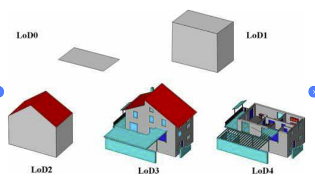
Figure 1. Five different LODs defined in CityGML.
2. Generating Building Footprints
Initially, Lidar point cloud data was obtained from the publicly available GeoNB website, focusing on a randomly selected study area within the Fredericton City domain. The ArcGIS Pro platform was employed to visualize the Lidar data, presenting high-density information encompassing point clouds for various elements in the study area, such as ground, low/high vegetation, buildings, noise, and et cetera. However, for the specific purpose of constructing LOD1, only building-related information was pertinent. To isolate this relevant data, the building point cloud information was extracted using the “Classification Code” section.
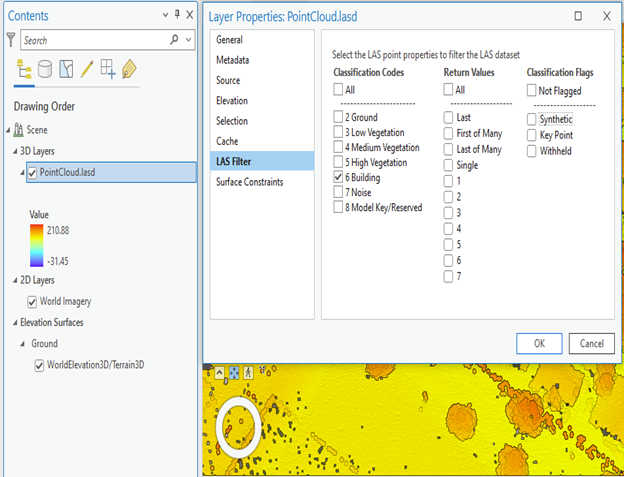
Figure 2. Layer Properties of point cloud data.
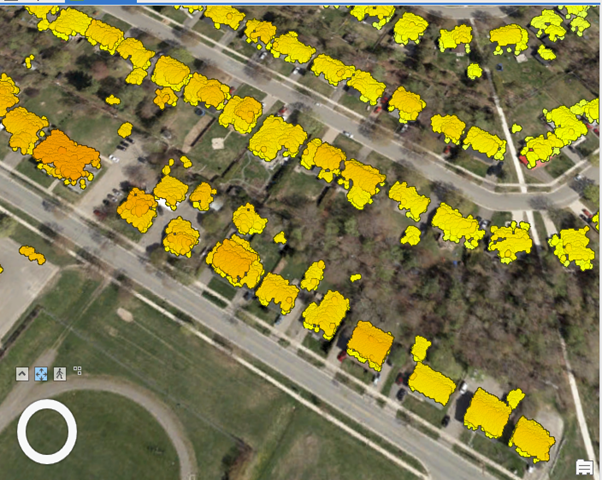
Figure 3. Building point cloud data
The “Las Point Statistics As Raster” tool was employed to transform the building point cloud into a raster format. Subsequently, the resulting building footprint rasters were converted into polygons utilizing the “Raster to Polygon” tool.
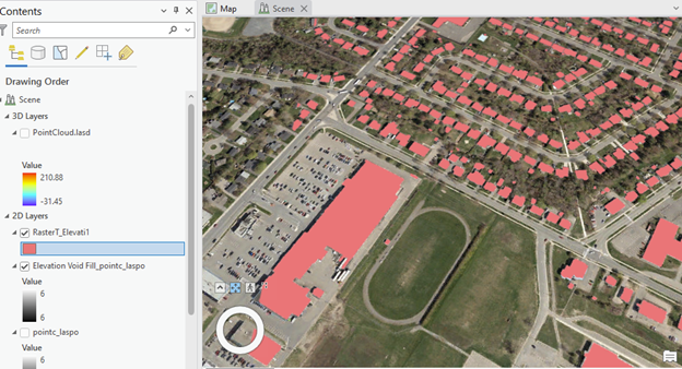
Figure 4. Building point cloud under raster format.
3. Constructing LOD1
The creation of LOD1 necessitated the development of a Digital Elevation Model (DEM) utilizing the existing Lidar point cloud data. Subsequently, both the Digital Terrain Model (DTM) and the Digital Surface Model (DSM) were generated, relying on Lidar First Return and Lidar Ground data, as illustrated in the figure below.
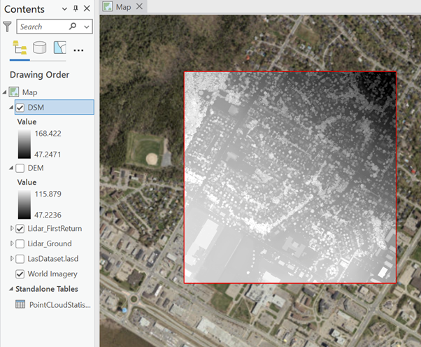
Figure 5. DSM and DEM information.
Height values were computed and extracted from the DEM and DSM. These values were then stored within the Building Footprint attribute table using the “Join Operator” tool. At this stage, the building footprint polygons had associated height values stored within their attributes.
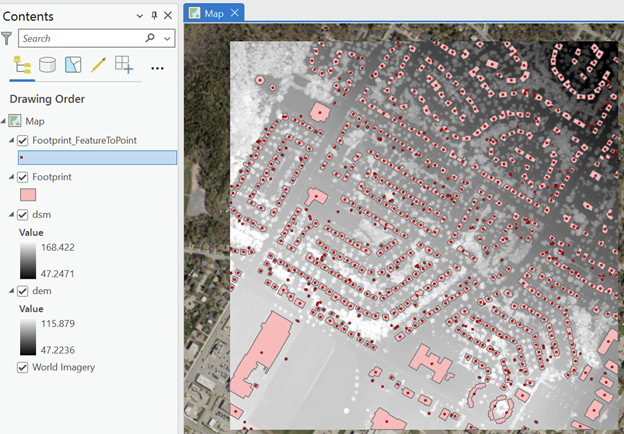
Figure 6. Storing height values into building footprints.
With this information readily available, the next step involved extruding the building footprints using the “Extrude” tool. Ultimately, the extruded polygons could be saved as true 3D data, referred to as Multipatch.
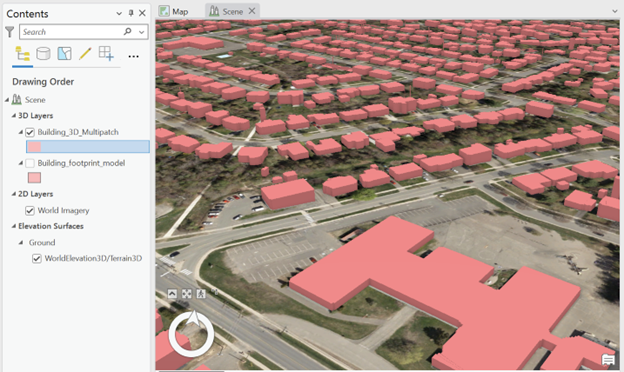
Figure 7. Final results of creating LOD1.
Honestly, witnessing the extrusion of a 3D building at the end of the process was a truly amazing experience!
References
1. Akmalia, R., Setan, H., Majid, Z., Suwardhi, D., & Chong, A. (2014, February). TLS for generating multi-LOD of 3D building model. In IOP conference series: Earth and environmental science (Vol. 18, No. 1, p. 012064). IOP Publishing.
2. GEONB Data Catalogue: http://www.snb.ca/geonb1/e/dc/catalogue-E.asp
3. Bramantiyo M – GEO 2004: https://www.fiverr.com/bram_juki