Fantasy Maps in ArcGIS Pro using Digital Elevation Models
Need a fantasy map? It’s easy to create your own fictional landscapes using digital elevation data from the real world! In this project, we’ll use the capabilities of ArcGIS Pro to create 2D and 3D fantasy maps, complete with contours, a river network, roads, villages, and sea routes.
Step 1: Acquire a DEM
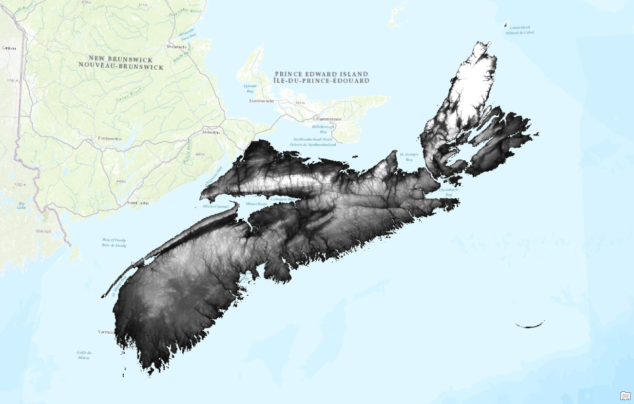
You’ll want a high-resolution Digital Elevation Model for this project. If you don’t have any datasets lying around, there are plenty of free sources available online! In this example, I use the Enhanced Digital Elevation Model of Nova Scotia, Canada (see Fig. 1).
Step 2: Define the Map Extent
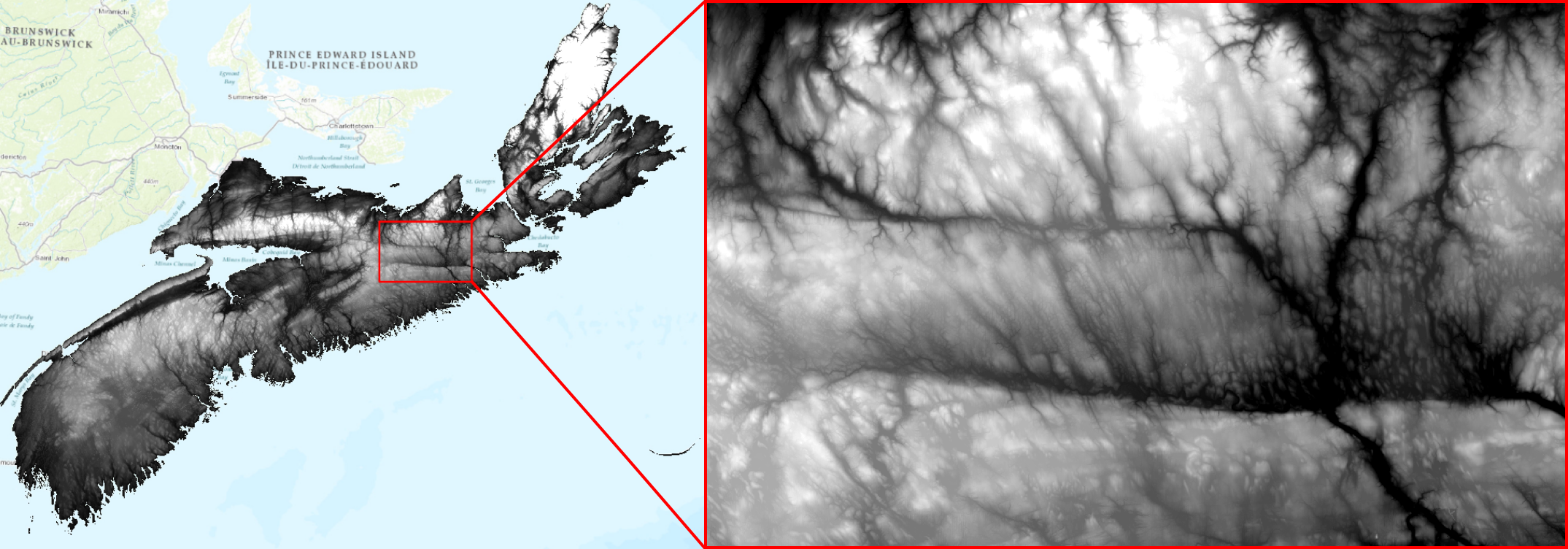
Zoom to an area with varied topography and choose the extent of your fantasy map. My study area was roughly 70 × 50 km, which resulted in a good level of detail in the final product. To isolate the DEM to the intended map extent, use the Clip Raster tool (see Fig. 2).
Step 3: Colourize the DEM
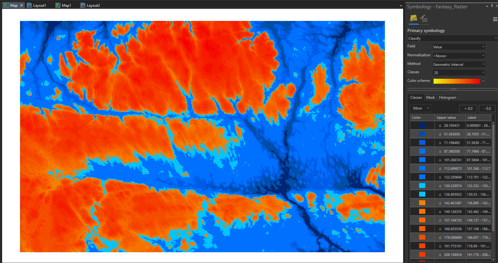
This is where the fantasy landscape begins taking shape! In this step, we will change the DEM’s colour scheme to simulate oceans and landmass. First, set the DEM’s Primary Symbology to “Classify,” which allows direct manipulation of the colour scheme. Next, change Method to “Geometric Interval” and Classes to “20” (you can increase or decrease this number to fine-tune the level of detail; see Fig. 3).
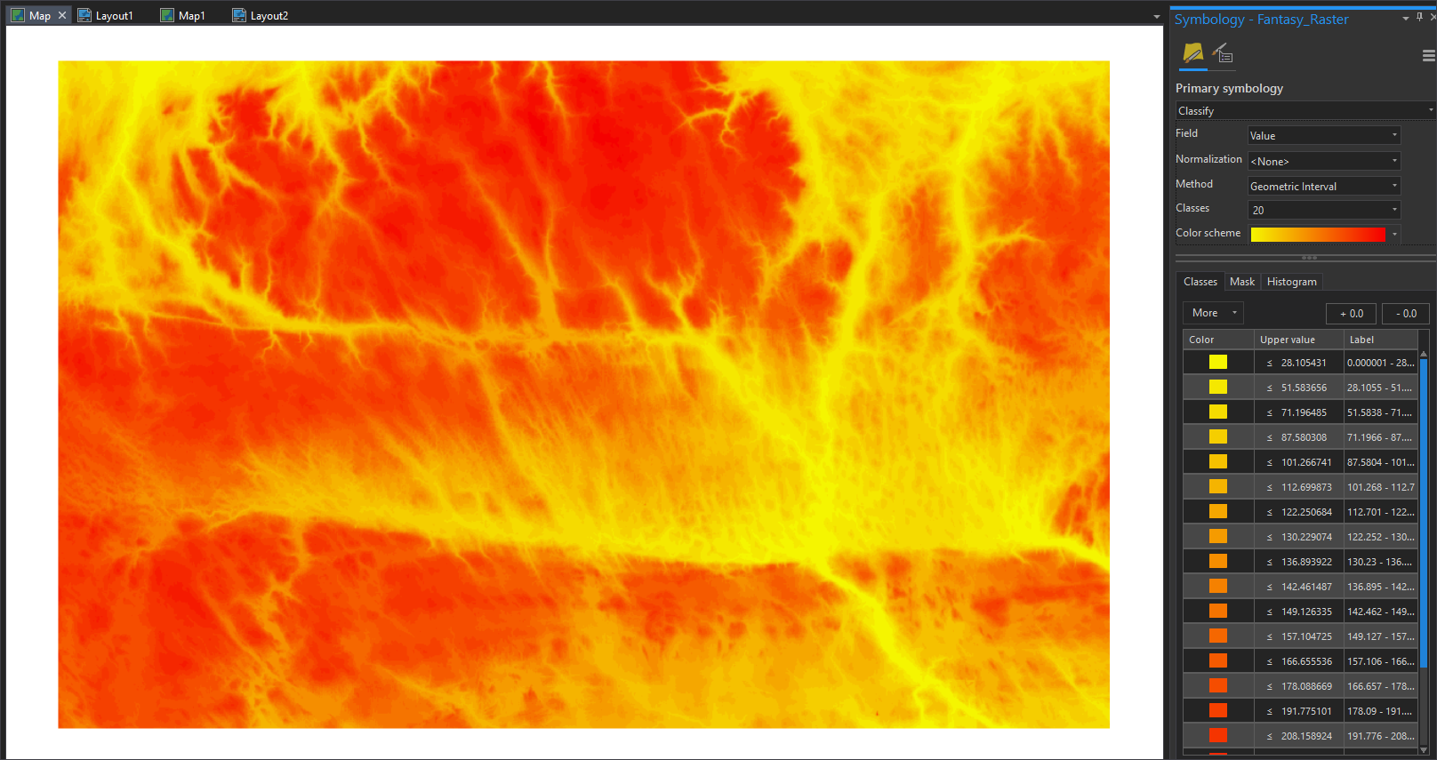
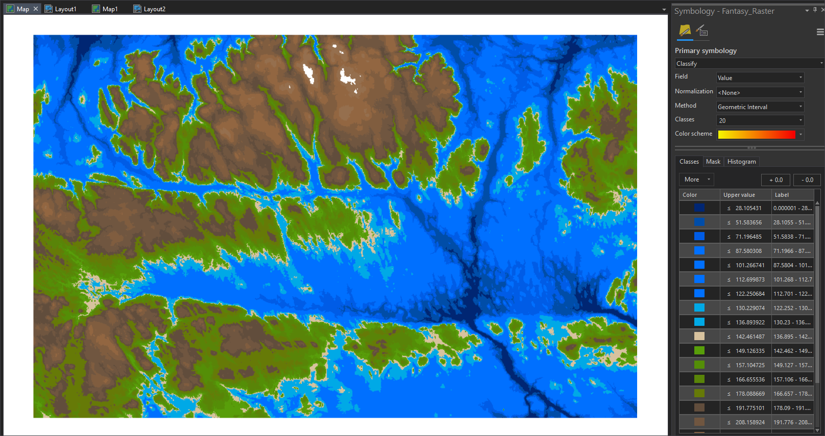
Next, we manually adjust the DEM’s colour scheme. Begin with a dark blue colour on the lowest elevation class (in this example, elevation ≤ 28.105431), which will become the deepest part of our “ocean.” Work up the classes with lighter shades of blue until satisfied with the ocean’s extent (in this example, a height of 136.894 meters; see Fig. 4).
With the ocean done, begin colourizing the landmasses. In this example, “low-lying” areas are painted various shades of green, while “mountainous” regions are brown, with white “snow-capped” peaks (see Fig. 5).
Step 4: HillShades and Contours
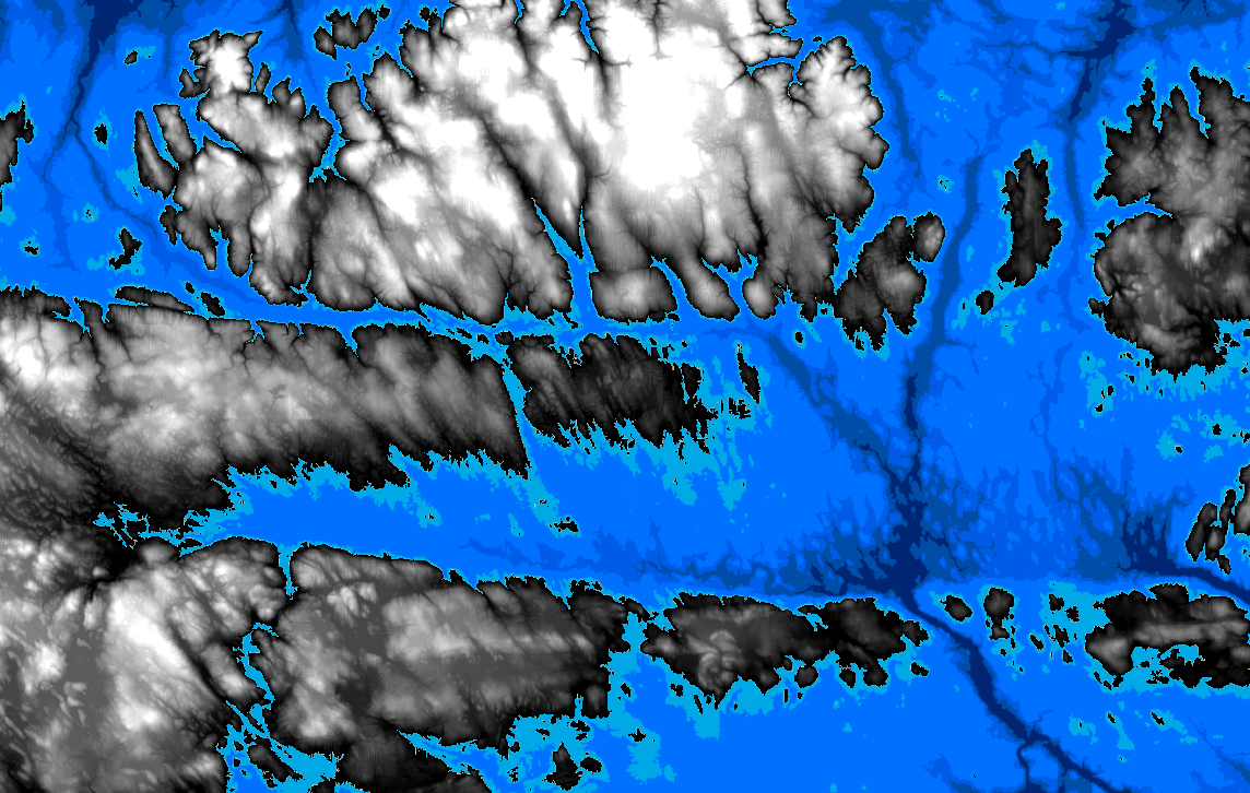
With the power of ArGIS Pro’s Image Analyst and 3D Analyst toolsets, we can add contours and a HillShade to give the map more detail. First, the clipped DEM raster must be altered, such that there is no topography below the “water-line” (I’ve found that “underwater” HillShades and contour lines look out of place). In this example, we use the Raster Calculator to set any values below 136.894 meters (i.e., the symbology class that denotes the start of the oceans) to Null via the following equation:
SetNull(“Fantasy_Raster” <136.894, “Fantasy_Raster”)
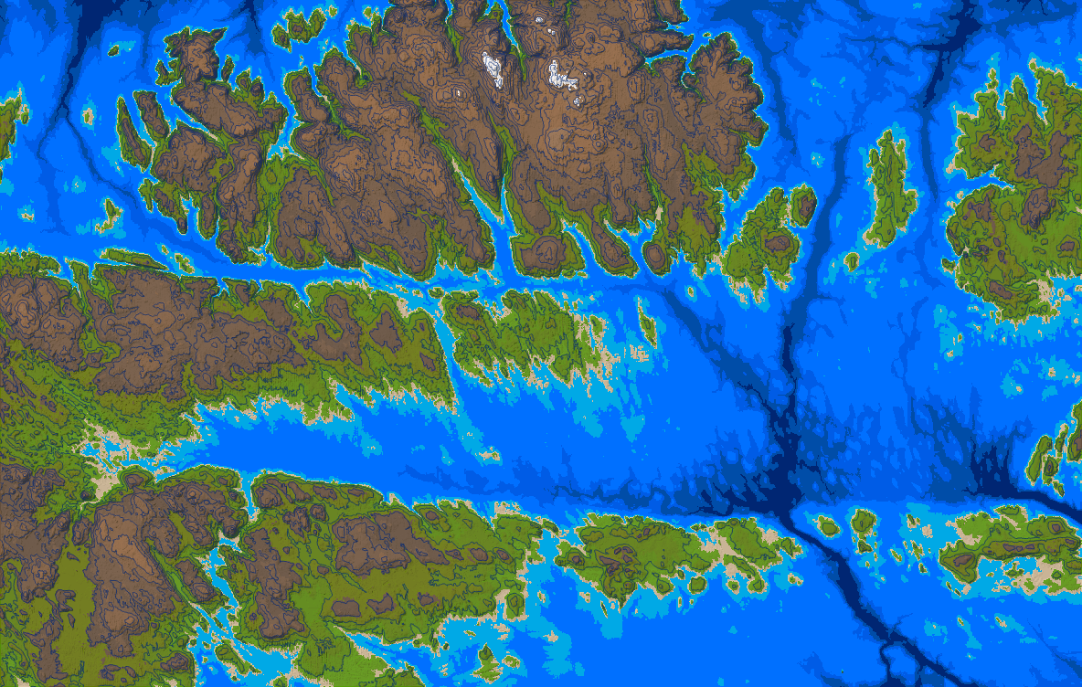
With this, we have a DEM that’s limited to the “landmass” as defined by our colour scheme (see Fig. 6). As such, we can now use the HillShade and Contour tools to add some extra detail to the map, using our “calculated DEM” as the input surface (see Fig. 7).
Step 5: Generating a Stream Network
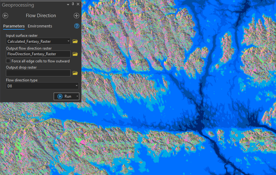
We can create realistic streams and rivers for our fantasy map using Spatial Analyst Tools (I followed this tutorial). First, a Flow Direction Model is created via the Flow Direction tool, with our “calculated” DEM as the input raster (see Fig. 8).
Next, the Flow Accumulation tool is used to calculate the accumulated flow within each cell (i.e., river locations), using our Flow Direction Model as the input surface (see Fig 9).

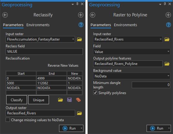
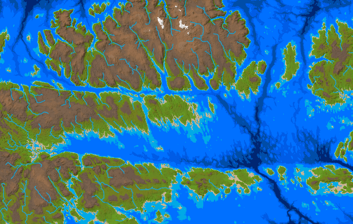
The map will look busy with too many rivers. As such, the bottom ~5% of cells from the Flow Accumulation Model should be removed using the Reclassify tool (in this example, cells with a value < 5000). Finally, convert the output into a line feature using the Raster to Polyline tool, which will result in the final river network (see Fig. 10-11).
Step 6: Populating the Map
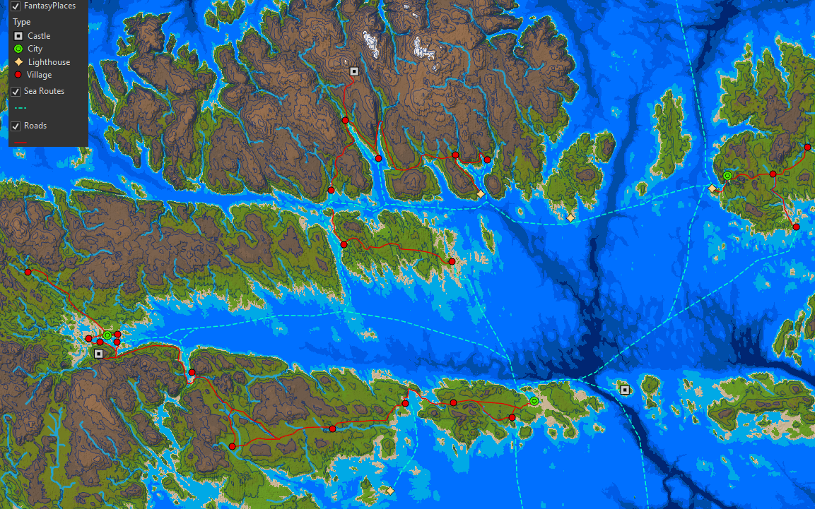
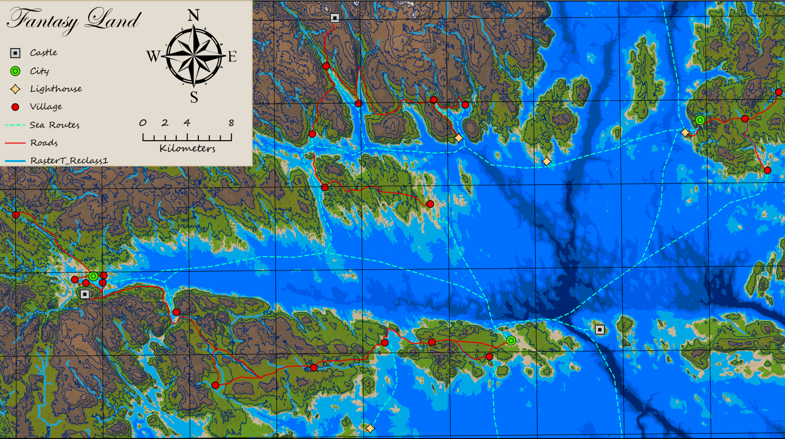
To make the world feel more inhabited, add some Point & Line features to represent roads, sea routes, and settlements around the map (see Fig 12).
Step 7: Layouts
Lastly, bring the final map together in a Layout, adding gridlines, a compass, scalebar, and a stylized map legend. ArcGIS Pro has lots of cursive-style fonts to choose from, which can help give your map a hand-made feel (see Fig. 13).
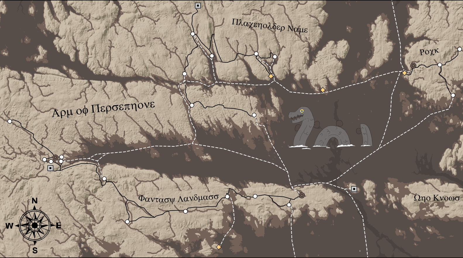
Keep in mind the stylistic choices shown here are just guidelines, and I encourage you to get creative! Just by changing some colours, placing text, and adding a friendly sea monster, I’ve created a whole new feel for the overall map (see Fig. 14).
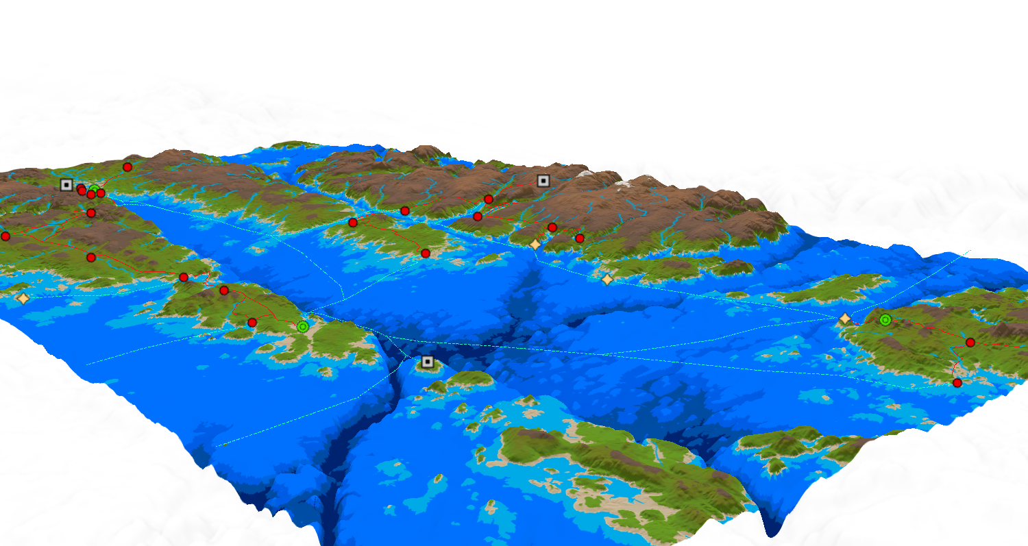
Step 9: Bring the map into 3 Dimensions
Another way to bring your fantasy landscape to life is to make use of the 3D capabilities of ArcGIS Pro! By copying the colourized DEM, HillShade, and point/line features into a Local Scene, the map can be viewed in 3D, providing a new perspective (see Fig. 15). In this example, I used the WorldElevation3D/Terrain3D Elevation surface with a vertical exaggeration of 10. Note for the point feature Properties, Elevation was set “Relative to Ground,” with no cartographic offset. In contrast, the road and river lines were set “Relative to Ground” with an offset of 100 meters, to prevent intersection with the ground geometry. Finally, for the sea routes, Elevation was set “At an absolute height” of 1500 meters to give the appearance of “floating” atop the water (it looks out of place if they follow seafloor geometry).